The next things I want to set up are to define the networks, as well as connect the hosts to shared storage. Before that, I want to create a new user so I am not using the included ‘[email protected]’ account.
Create New User Account
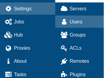
Go to Settings > Users.
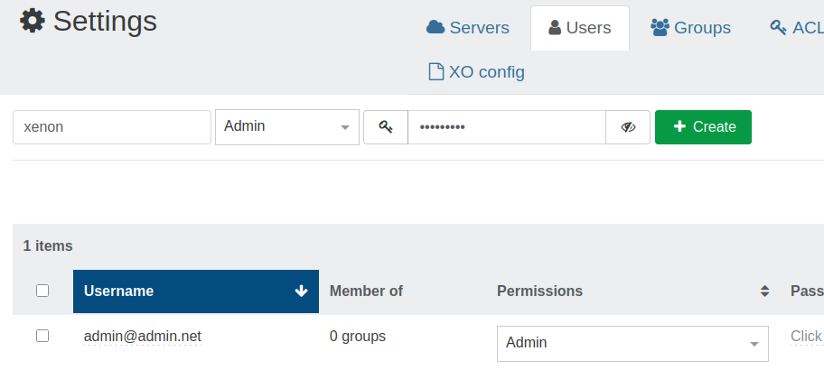
The existing ‘[email protected]’ account is listed below. To create a new account, use the boxes above to fill in username and password. Also, since I will be using the new account instead of the existing account, I click on ‘User’ in the drop-down menu and select ‘Admin’. Click ‘Create’ and it should show up below.
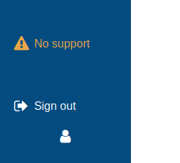
Click ‘Sign out’ in the bottom left, then login as the new user account. Click the red trash button next to the old account to remove it.
Define Networks
Think of networks here like a virtual switch between VMs and the physical network interface (PIF), or the last hop before the actual device. Common reasons to define networks within Xen Orchestra (and thus XCP-ng) would be things like assigning VLANs to VM virtual network interfaces, creating LACP bonds, etc. I will be focusing on VLAN networks, and more information on bonding can be found in the official documentation.
Networks are defined at the pool level, but they can be assigned and further configured at the host and VM levels. I will start with defining my VLAN networks at the pool level.
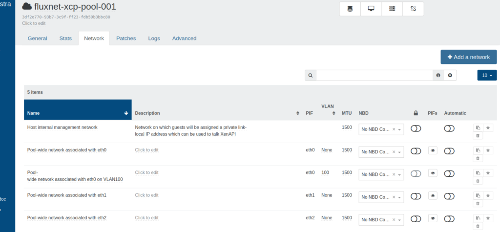
Go to Home > Pools. Click the desired pool, then the ‘Network’ tab. There are a few things going on here worth pausing before going any further.
Since this is at the pool level, each row listed in the bottom portion is an individual network.
- Name – This is an editable label for the network. It is worth it to give your networks a simple, predictable name as they will need to be selected in a drop-down menu when adding them to VMs.
- Description- This is optional and allows for more detail.
- PIF – Physical [Network] Interface
- VLAN – The VLAN ID is shown with VLAN networks, and tagged to any packets coming from VMs with that assigned VLAN network.
- MTU – Maximum Transmission Unit. Leave this at the default 1500 unless you really know what you are doing, else troubleshooting can be a nightmare.
- NBD – Network Block Device, useful for storage links (check official documentation for more information)
- 🔒 – Default locking mode. This is to lock VMs to only their allowed IP addresses, further configured at the VM level. Default here is off, or unrestricted. On would apply to VMs across the entire pool.
- Automatic – When networks are toggled, they are automatically added to new VMs.
The final three buttons are to copy network UUID, set as management network, and delete.
Quick note: The networks with names like ‘Pool-wide network associated with’ can be viewed like switch trunks. One is automatically created with each PIF. These do not add VLAN tags, so any VM with these networks assigned will also need to provide their own tags. However, if that VLAN is assigned as PVID on the switch port just beyond the PIF on the host, the switch port will handle adding the VLAN tag for any VMs that are assigned this network. Other VLAN networks can be created on that PIF as long as they are also allowed tagged at the switch port.
Click ‘Add a network’.
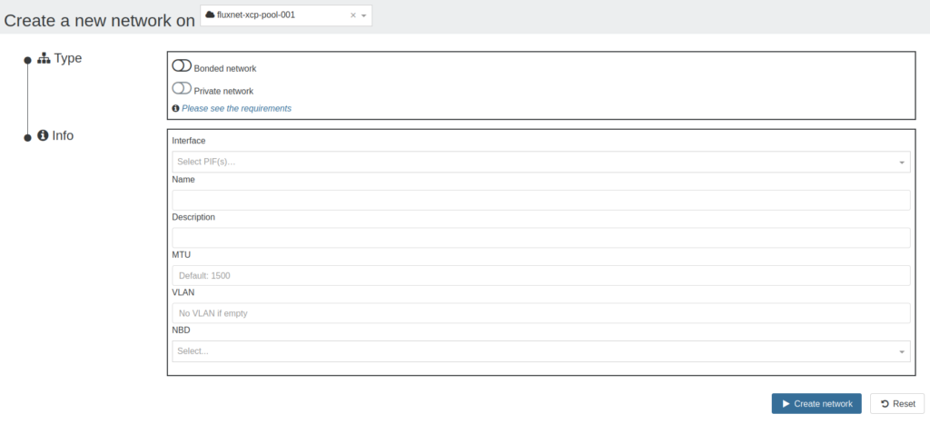
- Bonded network – Active/Active, Active/Backup, and LACP. Not used in this tutorial.
- Private network – This is a feature typically only available in XOA Premium, and relies on the SDN Controller plugin. It is for creating and managing pool-wide and cross-pool overlay networks with GRE or VxLAN encapsulation. Not used in this tutorial.
- Interface – Click the drop-down menu and assign to the appropriate PIF.
- Name – This is what is displayed when assigning to VMs, so keep it simple and predictable.
- Description – More detail.
- MTU – Not used in this tutorial.
- VLAN – Add VLAN ID here
- NBD – Not used in this tutorial.
Click ‘Create network’. Repeat for any remaining VLAN networks. In addition, I create network for storage on VLAN 250 on eth1.
Configure Networks at Host Level
Go to Home > Network, choose a host, then the ‘Network’ tab.

Each row here was either created with the network interface device itself, or created when Networks were defined at the pool level. They are simply either network interface, or network interface with a VLAN tag. Assigning IP configuration here to certain PIFs is very important so that hosts can talk to other hosts, or hosts can talk to storage. The management IP was set during installation, so all that is left here is to set an IP on the storage PIF.
Just like the last section, there is a lot going on here.
- Device – This is the name given to the actual physical device in Dom0. PIF is essentially one step above that.
- Network – Networks either created with device, or defined at the pool level.
- VLAN – VLAN ID assigned at the pool level when creating VLAN Network. This should be modified only at the pool level, unless there is a good reason.
- Address – IP address. Will be blank if not assigned.
- Mode – Defaults to ‘None’ and IP address will be left blank. Other options include DHCP and Static.
- MAC – MAC address of the PIF. Not editable here.
- MTU – Maximum Transmission Unit. Not editable here.
- Speed – Physical link speed
- Default locking mode – Similar to 🔒 at the pool level, but this applies to VMs on this host.
- NBD – Network Block Device. Indicates if NBD is configured on the Network at the pool level, and thus this PIF at the host level.
- Status – Green ‘Connected’ means PIF is enabled and network link negotiated, red ‘disconnected’ means no network link or is otherwise administratively down.
The final three buttons are to copy PIF UUID, assign as management PIF, and delete.
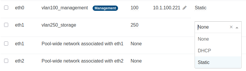
On the row for the storage PIF, click ‘None’ to open the drop-down menu and then select ‘Static’.
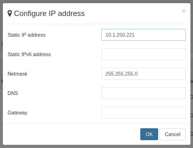
Configure IP address and netmask. DNS and gateway are not necessary since this subnet is isolated. Click ‘OK’ to continue. Navigate to the remaining hosts and repeat this process.
Now is a good time to SSH to one of the hosts and verify that it can ping the other hosts, as well as storage. Since this subnet is isolated, the host will know to use the only PIF that is actually connected to that network. However, time to do something unnecessary…
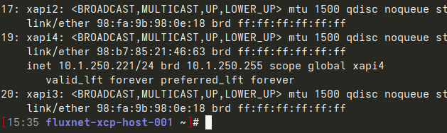
Instead of simply pinging the other hosts, do ‘ip a’ and find that the interface name here is ‘xapi4’.
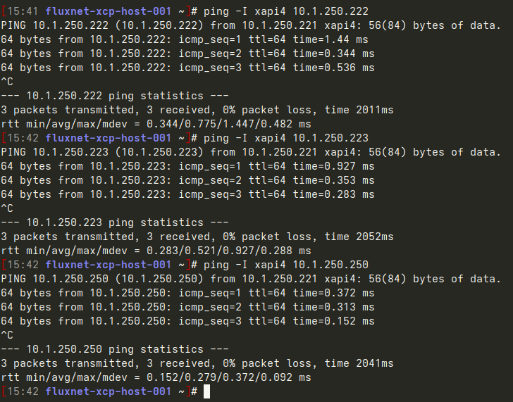
Then force the ping command to use ‘xapi4’ with:
ping -I xapi4 <host IP on VLAN 250>Adding and Configuring VIFs at the VM Level
Go to Home, or Home > VMs, choose a VM, then the ‘Network’ tab.
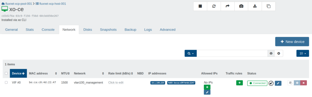
This is the place to add, remove, and configure virtual interfaces (VIFs) on VMs. VIFs are on other side of ‘Networks’ from PIFs. Each row here is a single VIF added to this VM, and will be presented inside the VM as its own network interface.
Again, there is a lot going on here:
- Device – Typically ‘VIF #’, followed by a number incremented with each new VIF
- MAC – MAC address for this VIF. This field is editable.
- MTU – Maximum Transmission Unit. Not editable here.
- Network – Defined at pool level. VLAN networks will apply tagging, pool-wide or ‘trunk’ networks will leave tagging to the VM or switch port.
- Rate limit – Used to restrict speed of VIF. Not used in this tutorial.
- NBD – Network Block Device. Shows whether this VIF is configured and capable of NBD.
- IP addresses – List of IPv4 and IPv6 addresses inside the VM reported by an installed management agent
- Allowed IPs – List of allowed IP addresses configured within the VM to be allowed on the network when locking mode is enabled. Click + to add an IP to the list, or click 🖉 to select from a list of IPs defined in an IP Pool within Settings > IPs.
- Traffic rules – Allow traffic based on port/direction. Functions as a very minimal firewall at the VIF level.
- Status – Green ‘Connected’ means PIF is enabled and network link negotiated, red ‘disconnected’ means no network link or is otherwise administratively down.
- 🔒 – The open lock shows that the default locking mode is disabled, and the blue edit box allows it to be changed between locked, disabled, network_default, and unlocked. Not used in this tutorial.
The final three buttons are to copy VIF UUID, enable/disable TX checksumming, and delete VIF.
Currently, XO-CE has a VIF with a 1Gb/s link speed, which is more than adequate for basic host management, but less so when it comes time to configure backups. I want to give XO-CE another VIF, this time on the storage VLAN.
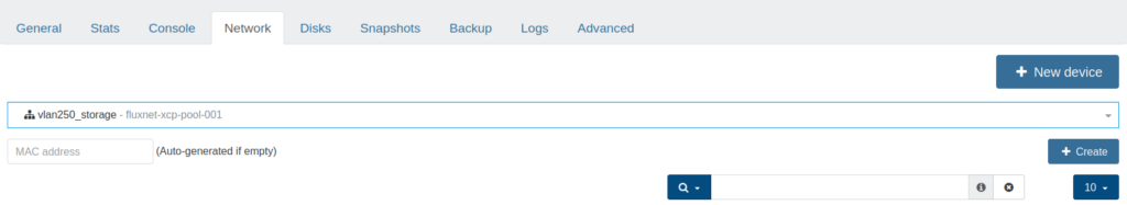
Click ‘New device’, then choose the Network for the storage VLAN in the drop-down menu. Click ‘Create’.
This VIF is not yet configured inside the VM. For that, SSH to the XO-CE VM IP.
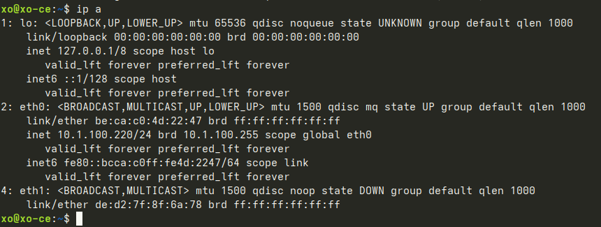
Type ‘ip a’, then enter to verify the interface name. In this case, it is ‘eth1’. Then open the network configuration file:
sudo nano /etc/network/interfaces(or use your preferred text editor)
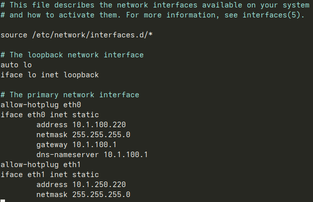
Create a new section for eth1, omitting gateway and dns. Save and close. Simply restarting the network in this case may cause the connection to drop, and may or may not come back. To be safer:
sudo rebootOnce the VM has restarted, SSH back and verify that the hosts and storage can be pinged from the appropriate interface.
Adding Shared Storage to the Pool
Now that the networks are defined, and the hosts and XO-CE are all communicating on the storage VLAN, it is time to connect the hosts to shared storage.
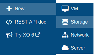
Go to New > Storage.
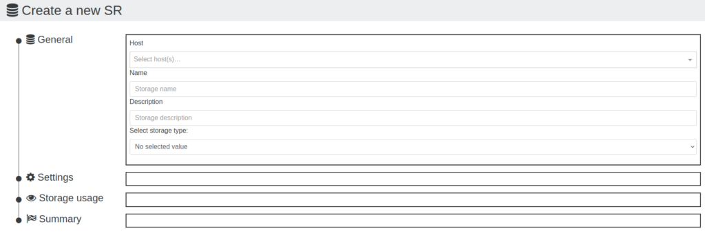
Select any host within the appropriate pool. The storage repository (SR) will be connected to each of them.
Create a name for the SR.
Create a description.
Select storage type
For VDI (VM) SR:
- ext (local)
- HBA
- iSCSI
- LVM (local)
- NFS
- SMB
- ZFS (local)
For ISO SR:
- Local
- NFS
- SMB
Here I will be using NFS to connect to existing SRs, so I choose VDI SR > NFS.
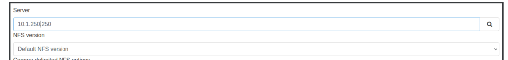
After selecting NFS, the options change in the Settings section. Type in the storage IP, ensuring that it is the one on the storage subnet/VLAN. Click the 🔍.
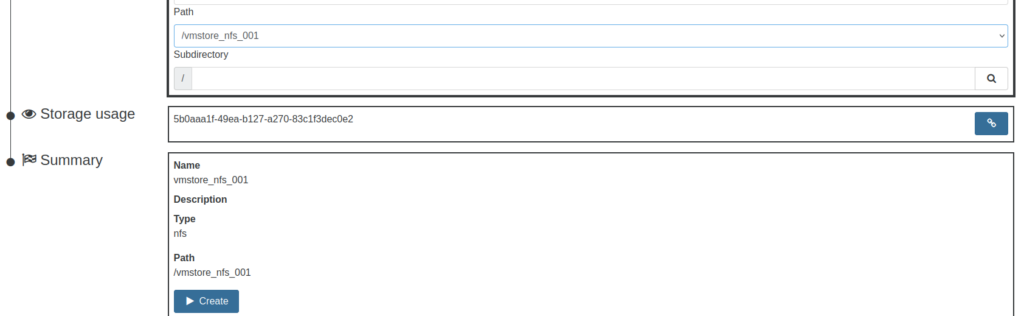
Click the Path drop-down menu and select the appropriate path. Since this path contains an existing SR, that SR UUID is displayed in the ‘Storage usage’ section, and I will not click the create button below. Instead, I will click the blue ‘Reattach SR’ button to the right of the SR UUID.
IMPORTANT: When reattaching to an existing SR, click the blue ‘Reattach SR’ button next to the SR UUID and do not click the ‘Create’ button below. This is less of a concern with NFS as creating a new SR simply creates a new directory with a new SR UUID within the same path. Simply repeat the New Storage process making sure to select the blue ‘Reattach SR’ button next to the appropriate SR UUID.
However, the same cannot be said for iSCSI SRs as creating a new iSCSI SR includes reformatting the filesystem. While there should be a warning if trying to create a new SR when one already exists, it is worth pausing before potentially breaking things irrevocably.
Repeat this process with any other SRs that need to be created and/or reattached.